Wind-assisted bulk shipping: from sea trials to port operations
Pyxis Ocean links wind-assisted propulsion with fuel measurement, port operations and the practical limits of a retrofit.
Published Mar 13, 2024
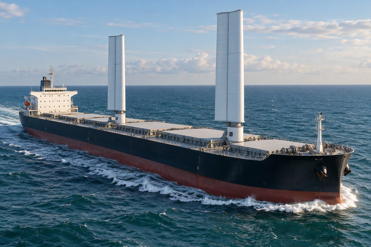
Pyxis Ocean completed six months of commercial voyages with two rigid WindWings supplementing its engine. The bulk carrier left Singapore in August 2023, crossed the Cape of Good Hope towards Brazil and travelled through the Indian, Pacific and Atlantic oceans before reaching Amsterdam in March 2024. Each steel-and-fibreglass wing stood 37.5 metres high. Cargill chartered the vessel, while BAR Technologies developed the equipment. The first operating results, published on 13 March 2024, put daily fuel savings at approximately three tonnes. The National’s Neil Murphy covered the trial.
Cargill estimated an average fuel saving of approximately 14 per cent, alongside a well-to-wake greenhouse-gas reduction of 11.2 tonnes of carbon-dioxide equivalent per day. Under favourable conditions, the fuel saving exceeded eleven tonnes a day. Automatic controls adjusted the wings, with a bridge panel and traffic-light system for the crew. Installation took place in Shanghai, China. The operator also engaged more than 250 ports over wind-assisted shipping arrangements. That work accompanied the vessel’s ocean passages and its continuing role as a cargo carrier.
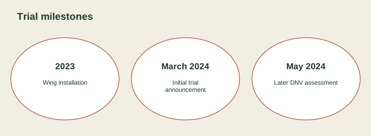
Illustration details
- Trial milestones
- 2023
- Wing installation
- March 2024
- Initial trial
- announcement
- May 2024
- Later DNV assessment
A rigid wing added to an existing carrier
Pyxis Ocean was built in 2017 and received its two wings in August 2023. The vessel measures 229 metres in length and 32.26 metres across the beam, with a deadweight of 80,962 tonnes. Its conventional propulsion remained in service during wind-assisted operation. The two wings automatically selected an operating configuration while the vessel continued carrying bulk cargo. The retrofit placed aerodynamic equipment on an existing ship, bringing wind propulsion into a working arrangement of hull, machinery and cargo space. The resulting installation operated across several oceans during its initial testing period.
Rigid wing sails generate aerodynamic lift and drag through the interaction between air and a shaped surface. Their geometry resembles an aircraft wing, and their orientation can change as the wind direction changes. Hard sails use strong, lightweight materials rather than the flexible fabric of conventional sails. Automatic rotation allows the surface to take up a suitable angle to the airflow. The aerodynamic geometry and the installation’s position both affect the forces produced. On a powered merchant vessel, those forces contribute thrust alongside the main propulsion system.
The engine and the sails work together
Wind assistance changes the load carried by the engine. At a given vessel speed, useful thrust from the sails reduces the propulsion work demanded from the conventional machinery. Main engines have a relationship between load and specific fuel consumption: their lowest fuel use per unit of output is associated with a particular operating region. When wind thrust lowers engine load, the engine can move away from that region. Total consumption and consumption per unit of engine output therefore respond to the combined operating condition of ship, sails and machinery.
Wind equipment also has its own energy requirements. Rotors require power to spin, suction wings use fans, and automated equipment operates control and positioning systems. Performance calculations combine these demands with the thrust supplied by the wind. At sea, the ship’s manoeuvrability and stability set operating limits. Stronger winds can increase available aerodynamic force while accompanying waves increase hull resistance and affect motion. In harsh conditions, wind-assisted systems can be taken out of operation. These operating states form part of the machinery and navigation arrangements for a vessel fitted with wind equipment.
Several ways to capture wind energy
Modern wind-assisted propulsion includes four prominent technology families: rotating cylinders, rigid wing sails, suction wings and towing kites. Each converts airflow into a force acting on the ship through a different arrangement. Rotors and suction wings stand on deck, hard sails provide a shaped lifting surface, and kites fly above the vessel. Their installation involves different combinations of supporting structures, moving parts and controls. The following equipment groups span those arrangements:
- Flettner rotors use a powered spinning cylinder and the Magnus effect.
- Rigid wings use an adjustable aerodynamic surface to generate lift and drag.
- Suction wings combine a wing-shaped body with fans and boundary-layer suction.
- Kites transmit aerodynamic force through a connection near the vessel’s bow.
A Flettner rotor produces lift perpendicular to the airflow around its rotating cylinder. Rotation changes the flow and pressure distribution, generating the Magnus force. Anton Flettner applied the principle aboard the ship Buckau in 1924, replacing conventional sails with two powered cylinders. Modern rotor installations add automated controls to the same basic physical principle. Their height, diameter and rotational operation determine the equipment’s aerodynamic characteristics. On merchant vessels, the cylinders stand on foundations that carry the forces into the ship’s structure while leaving the main engine available for propulsion.
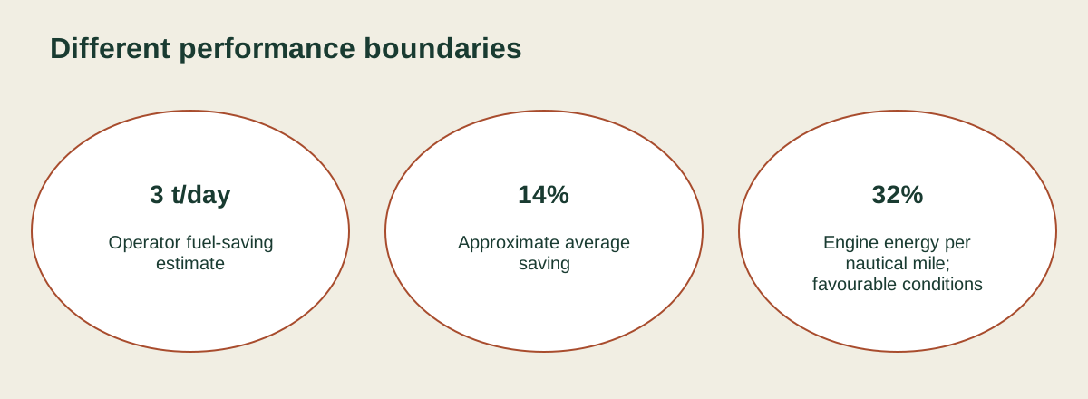
Illustration details
- Different performance boundaries
- 3 t/day
- Operator fuel-saving
- estimate
- 14%
- Approximate average
- saving
- 32%
- Engine energy per
- nautical mile;
- favourable conditions
Suction wings have an outer wing-shaped structure that does not rotate continuously like a Flettner cylinder. Internal fans draw air through openings to influence the boundary layer around the surface. The assembly can turn to align with the wind, and the fans support the generation of aerodynamic force. Installations vary in height and number of units. Small versions can be supplied in containerised arrangements, allowing the equipment to be transferred between vessels. Their mechanical layout combines the external wing, internal airflow machinery, supporting deck structure and automatic positioning equipment.
Towing kites operate at a greater altitude than deck-mounted wings and rotors. They connect near the bow and use aerodynamic lift and drag to assist the vessel. A passive kite follows the wind, while a dynamic kite moves through the air to increase the force generated. Automated systems handle launching and recovery according to weather conditions. Development trials have included separate take-off, landing, ascent and descent stages. The flying device, connecting system and launch equipment together form the propulsion installation, extending its operation above and ahead of the hull.
Deck access and cargo handling
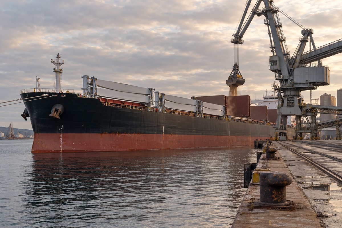
Bulk carriers fitted with wind equipment retain the need for cargo access. Several rotor installations address that requirement through movable foundations or folding structures. TR Lady received three rotors in June 2023, each 24 metres high and five metres in diameter. Transverse rails allow the units to move towards either side of the vessel during cargo work. The equipment’s seagoing position and its cargo-handling position are therefore mechanically distinct. Rail-supported movement provides one specific arrangement for clearing the working area around an existing bulk carrier’s cargo spaces.
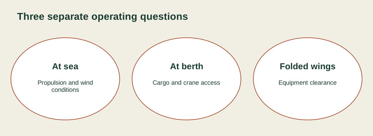
Illustration details
- Three separate operating questions
- At sea
- Propulsion and wind
- conditions
- At berth
- Cargo and crane access
- Folded wings
- Equipment clearance
Berge Neblina received four tiltable rotors in May 2024. Each unit measured 35 metres by five metres, and the installation took four days. The rotors can fold during cargo operations. Afros uses another movable arrangement: four rotors stand on carriage structures on the starboard side and can be repositioned for cargo handling. That Ultramax bulk carrier entered service in 2018. Folding and carriage systems supply different mechanical routes to the same operational task of accommodating wind equipment within a ship that loads and discharges cargo.
Retractable suction wings provide a further arrangement. Ankie received two such units in 2020, initially ten metres high and subsequently extended to thirteen metres. Their fans use two fifteen-kilowatt electric motors. The units can be lowered during port operations or when the ship sails into a headwind. The combination brings together vertical deployment, powered airflow and automatic wind alignment. Its arrangement differs from a rotor on rails: the equipment changes height rather than moving across the deck to another operating position.
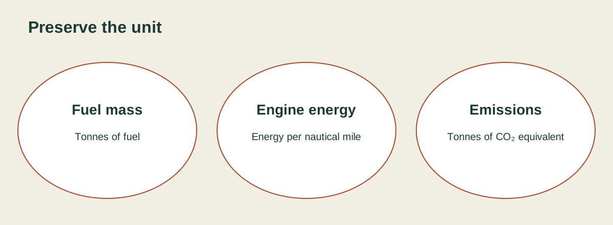
Illustration details
- Preserve the unit
- Fuel mass
- Tonnes of fuel
- Engine energy
- Energy per nautical mile
- Emissions
- Tonnes of CO₂ equivalent
Routing and the wind available at sea
Voyage planning for a wind-assisted ship incorporates wind speed and direction along the route. Research models combine vessel design information with weather forecasts and historical weather records. One routing study examined a very large crude carrier travelling between the Middle East and China. Another considered a post-Panamax vessel on a Brazil–China route, modelling wing sails, rotors and suction wings against weather records from 2015 to 2019. The calculations represented both the vessel’s performance and the equipment’s response to changing conditions along the passage.
Adaptive routing updates the chosen passage as weather information changes. Research into forecast uncertainty has used fuel-consumption calculations for more than a thousand departures over three routes. The response to weather uncertainty varied with voyage duration and wind conditions. Other models represent the interaction of hull, rudder, propeller and sails, including forces acting at drift angles. These simulations describe a moving vessel with several coupled components. Routing work therefore includes both the weather available along a passage and the response of the particular ship to that weather.
Aerodynamic interaction also occurs between neighbouring sails. Wind-tunnel experiments on paired rotors have examined their spacing, relative location and layout. Research on multiple hard sails has considered how wind direction changes interference between the surfaces. These are equipment-arrangement studies, using models to examine force generation before an installation’s operating performance is established. Vessel studies also investigate sail number and position alongside hull resistance and motion. The engineering work joins the aerodynamic layout above deck with the hydrodynamic behaviour of the hull in waves.

Tests, measurements and operating results
Sea trials record vessel speed, propulsion power, fuel consumption and emissions during operation with and without wind assistance. Numerical models estimate performance from sail thrust, wind conditions, route and vessel characteristics. Both approaches appear in the technical development of wind-assisted propulsion. Trials provide operating measurements, while simulations examine configurations and voyages through calculated behaviour. Demonstrator ships have been used to evaluate equipment in different weather and operational settings. Their instrumentation and recorded operating conditions supply the data used to compare the assisted and conventional propulsion arrangements.
Fehn Pollux received a single rotor measuring eighteen metres by three metres in June 2018. Leer University of Applied Sciences developed its monitoring and control systems and evaluated the installation during the first year of operation. The rotor’s additional power potential was in the range of 100 to 150 kilowatts. Measured fuel savings ranged from ten to twenty per cent, depending on main-engine power and vessel speed. Higher savings occurred at reduced ship speed. This operating example connects a specific rotor, vessel and test programme to recorded propulsion behaviour.
A later assessment of Pyxis Ocean covered favourable sailing conditions in May 2024. DNV Maritime Advisory found that the two WindWings reduced the main engine’s energy consumption per nautical mile by 32 per cent under those conditions. The result used a distance-based engine-energy measure. Earlier operating figures expressed fuel saved per day and an average percentage. These measurements describe the carrier’s wind-assisted operation through engine demand, fuel mass and greenhouse-gas accounting. The daily well-to-wake estimate includes emissions associated with the fuel supply chain as well as its use aboard the ship.
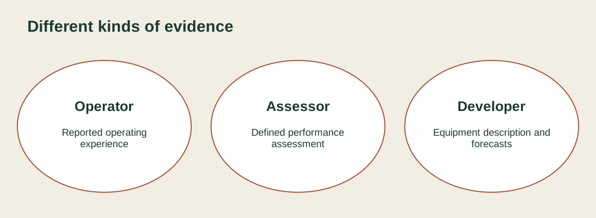
Illustration details
- Different kinds of evidence
- Operator
- Reported operating
- experience
- Assessor
- Defined performance
- assessment
- Developer
- Equipment description and
- forecasts
Preparing a ship for installation
Wind-ready construction incorporates preparatory changes before the propulsion equipment is fitted. These can include reinforcement of the deck and superstructure, changes to navigation equipment and modifications to electrical systems. An existing ship can also receive foundations and cabling during a scheduled refit. The wind equipment can then follow during a later yard stay or port call. This two-stage process separates structural preparation from delivery and fitting of the propulsion units. The preparatory work addresses the parts of the installation that must be integrated with the vessel itself.
Modular equipment extends that approach through units carried on flat-rack systems or in containers. Once foundations and structural work are complete, the propulsion modules can be fitted separately. Smaller containerised suction-wing installations illustrate the possibility of moving equipment from one ship to another. The resulting arrangement divides the installation into vessel preparation, module delivery and operational deployment. Modularisation is being developed alongside permanent installations and wind-ready ship designs, providing several ways to introduce wind assistance into an existing fleet or a new vessel’s construction programme.
Propulsion within the wider research programme
The EU-funded CHEK project combined operational technologies, power supply and drag reduction in bulk-carrier and cruise-ship concepts. University of Vaasa researcher Suvi Karirinne coordinated the work. Demonstration activity involved Pyxis Ocean and an MSC Cruises passenger ship. Proposed technologies included hydrogen engines, ultrasonic anti-fouling devices and route planning that used atmospheric and maritime conditions. Karirinne advocated combining technologies to reduce shipping emissions. The project’s researchers estimated potential combined reductions of fifty per cent in energy use and ninety-nine per cent in greenhouse-gas emissions, subject to applying the technologies together.
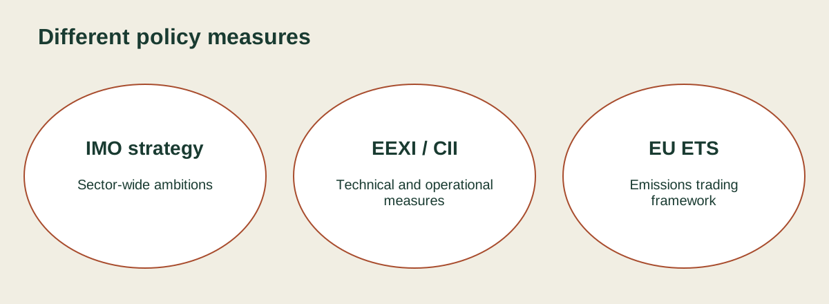
Illustration details
- Different policy measures
- IMO strategy
- Sector-wide ambitions
- EEXI / CII
- Technical and operational
- measures
- EU ETS
- Emissions trading
- framework
Twenty-four existing ships received wind retrofits and five newbuilds incorporated wind equipment in the 2018–2023 fleet group catalogued by February 2025. The separate group for 2024 and orders comprised twenty retrofits and fifty-two newbuilds. Bulk carriers formed the largest named vessel category, with ten existing applications and eighteen orders. The inventory included both earlier installations and projects awaiting delivery. Wind-assisted bulk shipping operated within a market that also included passenger ships, roll-on/roll-off vessels and tankers, alongside orders for the first installations on container ships and gas carriers.
Emissions policy and fleet operation
The IMO adopted its revised greenhouse-gas strategy in 2023, with an ambition to reach net-zero emissions from international shipping by or around 2050. Its indicative checkpoint for 2030 seeks a reduction in total annual greenhouse-gas emissions of at least twenty per cent against 2008, striving for thirty per cent. Technical and operational efficiency measures include EEXI and CII requirements, effective from January 2023. Maritime transport entered the EU Emissions Trading System in January 2024. These developments accompanied the growing use of wind-assisted propulsion on commercial vessels.
Vessel operators planning a wind retrofit deal with structural work, machinery integration and continuing operation of the equipment. The running requirements include power consumption, maintenance, surveys and crew training. Deck foundations and supporting structures form part of the retrofit engineering, while automated systems connect the wind equipment with the crew’s operating routines. Jan Dieleman, president of Cargill’s ocean transportation business, identified wind as a potential complement to lower-carbon marine fuels and cautioned that its suitability varies between trade routes. Pyxis Ocean’s trial combined that propulsion approach with commercial ocean passages and port calls.
Technical sections adapt and expand on Marcin Kolodziejski and Mariusz Sosnowski, Review of Wind-Assisted Propulsion Systems in Maritime Transport, Energies 2025, 18, 897, published 13 February 2025, under CC BY 4.0. Wording, selection and structure have been changed; no source photographs or diagrams are reproduced. CHEK context and the May 2024 assessment also draw on Tom Cassauwers’ Horizon reporting of 8 August 2024. Cargill’s March 2024 operating statement supplies the operator estimates.

Leave a comment